IPS 2.5K TWO CHANNELS PROFESSIONAL POWER AMPLIFIER
INSTALLED
IPS 2.5K
TWO CHANNELS PROFESSIONAL POWER AMPLIFIER
- 2 x 1250 W Class-H Power
- Fast response and low distortion
- Stereo, parallel, bridge modes
- Extensive protection circuit


Features
- 2 x 1250 W Class-H Power
- Fast response and low distortion
- Stereo, parallel, bridge modes
- Extensive protection circuit
- Variable speed cooling system
- Signal, clip, fault led indicators
- XLR input connectors
- speakON and binding post output connectors
- Limiter on each channel
IPS Series is a range of two channel professional amplifiers that combine the latest high-performing class-H power amplification technology with long-term reliability. IPS 2.5K is a 2-channel power amplifier that delivers up to 2 x 1250 Watts at 4 Ohms impedance. It features independent gain control, signal/clip and fault indicators, stereo XLR input and output link, stereo/parallel/bridge switch, speakON, and binding post output connectors. Moreover, it is protected against short circuits. Thanks to its high-efficiency heat sinks and variable speed fans, IPS 2.5K can withstand extreme heat conditions, ensuring complete reliability.
Read MorePart number:
12100059
IPS 2.5K
220-240V, EAN 8024530019617
12100060
IPS 2.5K
120V, EAN 8024530019624
Energize your Sound
IPS are high-performance, versatile 2U power amplifiers for install applications, using sophisticated Class-H topology for two single-channel outputs, two parallel outputs, or a single-channel bridge operativity. High quality, low distortion audio output, flawless reliability and safety, industry-standard speakON connectors, and binding post terminals make IPS Series electronics the workhorse solution for mobile sound systems and permanent installation applications.
Fast response and low distortion
Stereo, parallel, bridge modes
Extensive protection circuits
Variable speed cooling system
Signal, clip, fault led indicators
Limiter on each channel

The Advantage of Class H
Class-H amplifiers modulate the supply voltage to the amplifier output devices so that it is never higher than necessary to support the signal swing. This reduces dissipation across the output devices connected to that supply and allows the amplifier to operate with an optimized efficiency, regardless of output power level. Up to full power, a Class-H design will require less energy than a pure class AB design, and is better suited for high-power applications.
Remarkable Audio Performance
With a very high signal-to-noise ratio, IPS amplifiers also boast a very low total harmonic distortion, making it perfect for highly demanding music applications hence delivering perfect vocal intelligibility.

1 CH B OUTPUT
Channel B output to loudspeakers (SPEAKON and BINDING POST connectors). Do not use this output if the amplifier is set to BRIDGE mode. See both ‘Operation modes’ and ‘SPEAKON connector wiring’ manual sections.
2 CH A OUTPUT
Channel A output to loudspeakers (SPEAKON and BINDING POST connectors). If the amplifier is set to BRIDGE mode, only connect this output. See both ‘Operation modes’ and ‘SPEAKON connector wiring’ manual sections.
3 CH A INPUT
Channel A balanced audio input (female XLR connector).
4 CH A LINK
Channel A balanced parallel audio output (male XLR connector). This output is linked in parallel with the channel A input and is useful to link another amplifier.
5 SENSITIVITY switch
Set the sensitivity switch to either 0.775 V or 1.4 V, which is input signal voltage required to get the maximum power output from the amplifier.
6 CH B INPUT (STEREO MODE ONLY)
Channel B balanced audio input (female XLR connector).
7 CH B LINK
Channel B balanced parallel audio output (male XLR connector). This output is linked in parallel with the channel B input and is useful to link another amplifier.
8 MODE switch
Before turning the amplifier on, set the amplifier mode selector to the right position among BRIDGE, PARALLEL (mono) and STEREO. See the ‘Operation modes’ manual section.
9 RESET button
Push this button to reset the amplifier when is muted due to the thermal protection.
Self-protecting Architecture
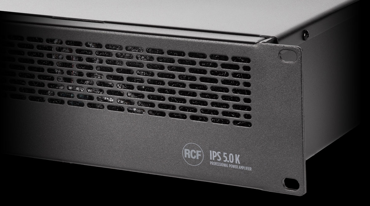
IPS Amplifiers implement several safety strategies protecting both the amplifier and the sound system, including an effective peak limiting protection for the transducers. The temperature-controlled continuous variable speed double-fan system (front to back), combined with the high-efficiency heat sinks, allows the amplifier to maintain the optimal working temperature, no matter the environmental temperature or the power output. The circuit is protected from overheating and short circuits, also including protections against infrasonic DC and Very High Frequency (VHF) peaks from non-musical signals that could damage transducers.
Amplifier specifications
Amplifier Class
H
Output Power
2 x 1250 W @ 4 ohm
2 x 800 W @ 8 ohm
1 x 2500 W @ 8 ohm (bridge)
2 x 800 W @ 8 ohm
1 x 2500 W @ 8 ohm (bridge)
Frequency Response (-3dB)
20 Hz - 22000 Hz
Crosstalk
<80 dB
Distortion (THD+N) @ 1 kHz nominal power
<0.01 %
Input section
Total number of inputs
2
Balanced
2
Mono
2
Line inputs
2
Line connectors
XLR
Output section
Signal output number
2
Signal output connectors
XLR
Power output connectors
Binding Post, Speakon
Configuration and control
Configuration
DIP switch, Front panel
Protections
Cooling
Forced
Short circuit
Yes
Thermal
Yes
DC
Yes
Fuses
Yes
VHF (Very High Frequencies)
Yes
Power requirement
Operating voltage
220-240/115 V~ 50/60Hz
Power consumption (MAX)
900 W
Standard compliance
Safety agency
CE compliant
Physical specifications
Cabinet/Case Material
Metal
Color
Black - RAL 9005
Rack mounting
19", 2U
Size / Weight
Height
88 mm / 3.46 inches
Width
482 mm / 18.98 inches
Depth
325 mm / 12.8 inches
Weight
11.2 kg / 24.69 lbs
Shipping information
Package Height
140 mm / 5.51 inches
Package Width
550 mm / 21.65 inches
Package Depth
530 mm / 20.87 inches
Package Weight
12.7 kg / 28 lbs
MANUALS
SPECIFICATIONS
STANDARD COMPLIANCES
Product Lines
Applications
Our Services
2025 Copyright ® RCF. All rights reserved | RCF S.P.A. cf/p.iva 04081310965


